

| 7. SKETCHED ANAGLYPH PICTURES |
A multitude of inquiries, many of them recent, indicate that that the interest in anaglyphic pictures, and especially in their construction, has grown. As some publications show, a spatial exhibition invokes better insights. For example, physical or chemical relationships become clearer in crystal patterns and atomic structures. With these there were and still are two problems: The actual construction of the drawings as such, and the subsequent "coloring" with matching anaglyph colors.
The spatial representation always requires two single views, which are quite similar, but not totally the same, where the differences depend upon the separation of the eyes and the distance to the picture. The more complicated the form of the object or image to be portrayed, the more work is required to calculate the small differences in the positions of the identical points in the single views that stem from the three x-y-z coordinates of the object.
Formerly, it was a tremendous task, requiring many consultations of values from trigonometric tables. Today, one can perform this a lot quicker and more precisely with the aid of computers, and can even leave the drawings up to plotters. These calculations can also be performed with scientific calculators, with low prices for the basic programmable models. The cited calculation programs are written for the TEXAS INSTRUMENTS TI 57, a popular, affordable programmable calculator. One can even attach printers onto somewhat more expensive devices so that even the note taking becomes superfluous.
The second problem lies with the drawings of the anaglyphs, especially in the assignment of the complimentary colors, usually blue-green and red (see chapter 5.2). The most trouble is caused by the blue-green since it is relatively translucent, not fully covering color which brings the color of the drawing medium, i.e., the writing, drawing or printing paper, into play. Naturally the color of the filters in the anaglyph glasses must be considered. Experimentation for each case is the only help.
In this context, the basic principle of anaglyphs is once again alluded to: the one color must match the corresponding color of the filter in the glasses so that it cannot be observed. It must, however, appear black with the opposite color. The latter is easy since a dark gray already acts like black. The former, specifically with blue-green, is not quite as easy. Often a light gray tone remains and can be disturbing.
From the preceding it follows that, under DIN 6170, where blue-green is required for the right eye and red for the left eye in anaglyph filters for glasses, the right single view must be colored red and the left single view blue-green.
A suitable paper is Reflex T 2000, a highly transparent drawing paper with a reactive surface. Suitable inks are Pelikan red, Pelikan light green, Pelikan dark green and Pelikan black for the lines in the picture plane. Blue-green toners: Light green and dark green diluted with small portions of distilled water: 1 part ink to 1 part water. From these dilutions one then mixes 2 parts dark green with one part light green. This basic mixture is then tested against the selected paper with the help of the glasses. It is adjusted through the addition of either light green or water. An eye dropper is a handy tool.
The choice of colors for blue-green with the filter of the glasses can be only a compromise, a residual image is always present. Ultimately it is a matter of contrast versus background. The toning is depending on the paper, red/green glasses, and lighting. The contrasts change when dark to black paper instead of light paper is used as the base of the anaglyphs. These are called negative anaglyphs. Green viewed through a green filter "disappears" against a light background, green viewed against a dark background is clearly distinguishable. The complementary colors then exchange their roles. During the examination of the color choices, it must be taken into consideration that the combination of the green color and the red filter as well as the red color and the green filter appear as dark as possible. Red color and a green filter work well together, green color and a red filter do not.
New problems arise with the printing of negative anaglyphs. Red and green lines may not be printed but must be marked off against the surface, in about the same manner as in intarsias. For people wishing to draw negative anaglyphs, opaque colors, which allow nothing of the black undercoat to show through, are required. Because of their consistency, these covering colors cannot be manipulated with tubular quill pens. The old, adjustable, drawing pen is ideal. Especially suited are the luminous colors: white, red, green and blue. When working with the drawing pen, the colors must be diluted with water to a point where they just begin to drip. Green requires a small addition of blue. Here, testing is also advised.
The transfer from the calculated picture drawn on graph paper to the black cardboard ensues with the aid of a needle. The intricate holes are marked with white ink. the positioning of a ruler is then no longer a problem.
The negative anaglyphs become especially impressive when viewed in a darkened room under UV-lights. In addition to the beautiful effects, new practical application are also possible. Two possibilities are: Eye examination and photography. Photographs created in such a manner do not produce quite the effect that luminescent colors do, but it has been shown that with the red/green glasses the spatial image reappears. Because of the fluorescent light and small bright areas, it is best to take some test exposures. A light meter provides only a rough estimate of the exposure time.
Positive and negative anaglyphs can be overlaid if they were created with equal projection values (base, separation). The positive anaglyphs must be drawn onto transparent paper. The sketches must contain orienteering marks so that the first spatial image correctly blends into the second. The x-axis in the ground plane is recommended as an orienteering point because it is from here that the viewing position of the eyes with distance d and height h is established. Both sheets are covered with a thin plate of glass so they remain fixed and do not contain any air bubbles. All lines appear dark upon a light background. This procedure is especially interesting when geometric dependencies are being studied.
Transparent paper on a black surface is still perceived as "dark" with negative anaglyphs. With the positive anaglyphs on the other hand, the background is evidenced as being "light". The result is then a bright, stick model in which a dark stick model is implanted With this, one obtains a good differentiation between the two parts of the picture. Since the dark lines of the positive anaglyph are more evident because of the increase contrast, one must decide which part of the picture should be represented by the negative anaglyphs and which by the positive ones. By using a combination of lights - lamp light and UV light - the picture gains in luminescence.
Two works by Prof. R. Burkhardt (Institute for Photogrammetry, TU Berlin), with regard to the red/green glasses, give some information of the problems of interaction between the paper, printing color, filters and the physiological characteristics of the eyes: The color measuring of anaglyph glasses and study on anaglyph printing colors (1972).
Photographic filters of many diverse shades are available from LEE-FILTERS company, Andover, England. Filters suited for the red/green glasses are: Primary red No. 106 and Primary green No. 139. When viewing negative anaglyphs under UV-light, a supplement of fluorescent green No. 219 can be advantageous.
The finished but not yet colored, single views should now be checked for the correct spatial format with a stereoscope (displacing a single view on the x-axis). With this one must consider that since the anaglyph projections are in the ground plane, a certain amount of distortion takes place. With a normal lens stereoscope this is possible only if the single views are not any larger than 6 x 6 cm. For anaglyphic viewing, however, the format can be as large as desired, which is the main advantage. One can now reduce the single views. (In almost every photocopying center there is a machine that reduces to smaller sizes, and sometimes even enlarges, i.e., by a factor of 0.71 or 1.41, for example. This can be repeated until the desired format has been reached. However, one could also construct a mirror stereoscope (see fig. 5.14) or view the pictures one above the other with prism glasses (see fig. 5.15).
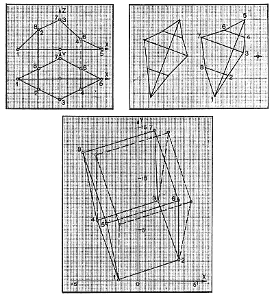
The bulk of the work must be spent on determining the spatial coordinates of the object to be drawn and on the painstaking recording of the data. One numbers all of the required points in a certain order and constructs an appropriate table (see the example later in this chapter). It is best to begin with the easiest location in the coordinate system where the xyz-values agree with the dimensions of the object. Only then does one shift everything onto a symmetrical axis so that after rotation the object into the most advantageous position for the picture, the new xy-values are easier to calculate (see the program for this). One must keep in mind that the measurement of the object must be correct to a tenth of a millimeter because this can be easily reproduced when drawing on the graph paper. The trigonometric values are rendered to many decimal places by the calculator so that the result has a corresponding number of places after the decimal point. These, however, are not required. They are rounded to the nearest tenth of a millimeter, or one can program the calculator so that only one decimal point is displayed (button Fix1). Finally, one moves everything on the y-axis behind the xz-plane so that one does not have any negative y-values.
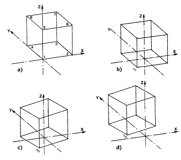
Figures 7.1a - 7.1d, as well as figure
7.2, shows an example of the steps involved in the transformation of the
x- and y-values of a cube into the x3 and
y3 values required by the calculation program
(also see the table later in this chapter). Figure 7.2 probably suffices
for technically schooled people that are used to imagining objects from
drawings in one plane. Figure 7.1 attempts to shows this through perspective
drawings.
|
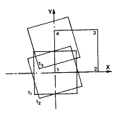
to the plane Figure 7.2
|
||||||||
|
|
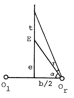
Even in anaglyphs the amount of depth of field,
t, in relation to the near-point, E, and the base, b, plays an important role.
So that no double pictures appear, all of the elements in the picture that create
the overall impression must lie within the panum area of the eyes. The object
must lie within a viewing angle ![]() .
This angle is reported as 70' = 1.17°
.
This angle is reported as 70' = 1.17°
| (b/2)² + e² |
|
||||
|
|
|
|
|
|
for a base of 6.5 cm. |
|
|
|
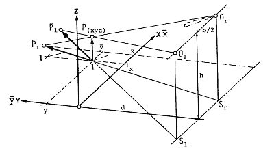
The value e is made up of d, the separation
of the standing line and the main x-axis + the smallest value of y3
from the table. In regard to the already calculated cube, d = 30 cm and
y3 = 0.15 cm.
| 10 + 30.15² |
|
||||
|
|
|
|
|
|
= 7.4 cm |
|
|
|
This value is greater than the length of
the cube, 6 cm. The angle is constructed from the connecting line T - Or
- l shown in fig. 7.5 which also shows the position of the other labels.
|
|
|
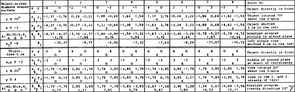
Notes to the table:
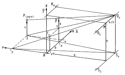
The given image equation hold for anaglyphs intended to be viewed in a book. During the calculation one imagines the object - or the model of the object - standing on the ground plane (x;y) in about the first octant (space is geometrically divided into 4 positive octants above the ground plane and 4 negative octants below the ground plane) and projecting from the two eye points Or and Ol onto the ground plane. From experience it is known that front pictures provide little viewing quality. Therefore the object is s that a favorable viewing direction results. The ordering of the coordinates was chosen that the unchanged coordinate - here the z-coordinate because of the rotation about the z-axis - is easily recognized. The following shift in the x-direction towards the left was also due to viewing reasons, but point 3 still lies in the first octant. An additional shift in the y-direction would also be reasonable so that the object entirely behind the x;z-plane when viewed from O. How large the shift should be becomes evident only after the execution of the first rotation. In the valuation of the image equations A(h,d,b) the ordering xr, xl was chosen since with these anaglyphs the left single views lie on the right and the right single views lie on left. With the shift x1T-6 the single views are separated.
This process is not always necessary. When
viewing the results one should note that the undistorted pictures are seen
only when the initial image values, distance d and height h and picture
in the ground plane, are obeyed. Different image equations hold for projection
onto a perpendicular screen (see later in this chapter).
The Cube as Test Picture
The picture of the cube serves not only
as a means of proofing the image with regard to the creation of the spatial
image and the elimination of distortion when the image values are adhered
to, but also as a template for the development of new pictures. The picture
of the cube marks out the entire space in which one could place a new model
and gain an image of the staked out size (see fig. 7.8).
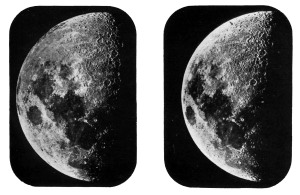 Figure 7.4 THE MOON IN 3-D taken with a time interval of quite four years 1st picture: April 20th, 1896, 8h, 18', 3" 2nd picture: February 7th, 1900, 6h, 15' 30" Libration (oscillation of the moon axis) 15° Place: Equatorial Coudé, Paris |
Rotation of Points about the Origin in a xyz-Coordinate-System
Clockwise: ![]() technical totation about the angle
technical totation about the angle ![]() .
.
Counter Clockwise: ![]() mathematical rotation from the 1st to the 2nd quadrant.
mathematical rotation from the 1st to the 2nd quadrant.
| Clockwise: |
Counter Clockwise: |
The above example deals with a rotation about the z-axis. With totations around the x- or y-axis the corresponding labels of the other axes must be substituted:
by x : ![]() / x / z;
/ x / z; ![]() / y / z; by y :
/ y / z; by y : ![]() / x / z ;
/ x / z ; ![]() / x / z;
/ x / z;
Calculation program:
|
|
enter memory values
|
||||||||||||||||||||||||||||||||||||||||||||||||||||||||||||||||||||||||||||||||||||||||||||||||||||||||||||||||
Literary References:
(1) R. Sachsenweger, Stereo-Sehübungen,
ein Bilderbuch für Kinder von 4 - 10 Jahren; Fischer-Verlag,
Stuttgart 1977
(2) U. Graf, Konstruierte Anaglyphen,
Deutsche Mathematik 1911/2
(3) Schwidefski u. Ackermann, Photogrammetrie,
Teubner-Verlag, Sttuttgart 1976
(4) J.P. Frisby, Seeing, Illusion, Brain
and Mind, Oxford University Press 1979
(5) R. Schmidt, Lehre der Perspektive
und ihre Anwendung, Bauverlag Wiesbaden, Berlin 1978
(6) R. Schmidt, Darstellende Geometrie
mit Stereo-Bildern, Bauverlag Wiesbaden, Berlin 1977
The Image Equations for Anaglyphs (Book Anaglyphs)
Directions for construction of anaglyphs are found in Schmid, Lehre der Perspektive.
The equations:
|
|
|
|
||||||||
|
|
|
|
|
|
|
|
|
|
|
|
|
|
|
|
when z = =, then ![]() = x and
= x and ![]() = y, i.e. in the ground plane
the pictures coincide with the original points.
= y, i.e. in the ground plane
the pictures coincide with the original points.
Calculation Program for Image Equations "Anaglyphs"
|
|
enter memory values
|
||||||||||||||||||||||||||||||||||||||||||||||||||||||||||||||||||||||||||||||||||||||||||||||||||||||||||||||||||||||||||||||||||||||||||||||||||||||||||||||||||||||||||||||||||||||||||||||||||||
|
|
Stereoscopic pictures "Anaglyphs" (picture in the ground plane) |
The Image Equations for Stereoscopic Pictures
Picture plane is perpendicular to the ground plane (Stereoscope, Projection).
The equations:
|
|
|
|
||||||||
|
|
|
|
|
|
|
|
|
|
|
|
|
|
|
|
Calculation Program for Image Equations "Stereoscopic pictures"
|
|
enter memory values
|
|||||||||||||||||||||||||||||||||||||||||||||||||||||||||||||||||||||||||||||||||||||||||||||||||||||||||||||||||||||||||||||||||||||||||||||||||||||||||||||||||||||||||||||||||||
|
|
Stereoscopic pictures (picture perpendicular to the ground plane) |
|
After calculation of the kite-shaped
surface, the left single view was shifted toward the left by 6 cm. A stereo
picture of the surface, which can be viewed with a stereoscope with lenses,
originates in this way.
In order to obtain anaglyphs, place a piece of transparent paper on the right single view and draw out the exes of the figure in black and color the remaining lines with red. Set the sheet with the red dolor onto the left single view so that the points 1 and 5 lie upon each other. Trace over with green ink. The cube is shown as a book anaglyph, but naturally is not printed this way because of the cost. Therefore it cannot be spatially viewed. |
|
broken kite surface, base coordinates and stereo picture Figure 7.8 (below)
|
Colored pens can be used instead of colored inks mentioned earlier in this chapter. The green "Schwan-Stabilo HL 66" markers are ideal. For better coverage one should draw two lines in place of one., which can be tricky. The red "Edding 1701 M red" is ideal. The green lines must be drawn first, however, otherwise some of the red is carried into the green lines when they cross. This combination is especially well suited for viewing under lamp light.
For daylight viewing one should expose the green drawing to sunlight for 1 - 1½ hours before drawing the red lines . This causes the green to lose a great deal of its luminescent quality.
The green colors of "Schwan-Stabilo Boss" and the sunlight-sensitive red color from "Faber-Castell textliner 48 fluorescent" are ideal for extremely large drawings requiring a line width of 5 mm.
Pens suitable for anaglyph transparencies
are "Schwan-Stabilo Pen 96 P Fine, 196 Superfine Permanent Red and Green".
"Rotring ink K 595 703 Red and K 595 707 Green" can be used in place of
pens. These bind to drawing material and therefore produce lines which
do not smear. The green must be thinned with dilution K 595 290 in a ratio
of approx. 1 : 1. A piece of blotting material must be placed in the tip
of the drawing pen in order to achieve an even line. Otherwise the pen
dries out quickly. Raster films from LETRASET Project-a-tone PTT red and
green can be used as a supplement to the figures if special surfaces must
be covered.
| Previous
Chapter: 3-D Movies: Exposure and Projection |
Contents |
Next
Chapter: Do-It-Yourself Directions |
|
 |
|
|

| Back to the Services Page |